In this part we will go through the re-assembly of the rear axle and the parts and tools used to accomplish this. Getting things back together can be kind of tricky and can take a little time but, if done right, will make for a good solid quiet running rear end. If you missed Part 1 of this rear axle rebuild, we recommend you check it out.
For our build we will be replacing all the bearings and seals, as well as the ring and pinion gears. The original gears in the axle were 4.10:1 gear ratio. Since we will be going to a 35 inch tire, we wanted to adjust the gearing a bit to compensate for the larger tires. The new ring and pinion set we will be putting back in are 4.56:1 gears. All the bearings and seals we use are Timken.

To start off with we will make sure that the differential area and axle tubes are cleaned up and free of any dust, dirt, and debris. After that was done we installed the axle shaft bearings in the ends of the axle tubes using a bearing/seal driver. Using a tool similar to this will help insure you do not damage the bearing while driving them in the axle tube and seating them properly. There are 2 different sizes of bearings for a GM 12 bolt axle so be sure you get the right size bearings for your axle. Our bearings are Timken 6408 which have an outside diameter of 2.531 inches and the seal is Timken 8835S. The same tool can be used to drive the seal into the tube as well.
You may have to change the size of the drive head but again that same bearing/seal driver can be used to install the races for the pinion bearings. Find the head piece that fits the race you are going to install the closest and gently drive the race into the differential housing. The outer pinion bearing race is Timken part number M88010, and outer pinion bearing is Timken M88048. The inner pinion bearing race can be installed with the bearing/seal driver as well. This one may be a bit more difficult, as it is a longer reach into the case to install the race. The inner pinion bearing race is Timken HM89410 and the inner pinion bearing is Timken HM89449. A tip I learned from Eric The Car Guy’s Youtube channel is to buy 2 of the outer pinion bearings and then grind the inside of 1 of the bearings out slightly so that it does not fit so tight on the pinion gear. This will facilitate easier dis-assembly if you need to add shims to the pinion or differential. Once you get everything adjusted and shimmed where it should be this bearing can be replaced with an unmodified one before final assembly.

We took the carrier apart and cleaned up all the pieces in the parts washer. As we were putting the carrier back together, we applied some oil to all the contact surfaces. This provides a bit of pre lubrication prior to the case being filled with oil, which will aid in assembly later on. Once all the spider gears were placed back in the carrier, we installed the ring gear on the carrier. We saved all the original bolts and cleaned them up for reuse during re-assembly.
When putting everything back together it is a good idea to use some thread locker. You can use the red stuff Loctite 271 which is permanent. This will come off if heat is applied from a torch or heat gun. The blue stuff, Loctite 242, is medium strength and removable without application of heat. We will be using Loctite 242 on all the ring gear bolts. The torque spec we used was 55 ft lbs for the ring gear bolts. One thing to keep in mind is, thread locker of any kind usually likes to be applied to clean dry threads. Inside the differential housing of your axles is the last place you want a bolt coming loose, so thread locker of some sort is a good idea here on all bolts. When first assembling the rest of the parts in the differential, don’t use any thread locker quite yet. You may need to dis-assemble things once or twice to get the backlash and contact patterns where they need to be.
With the pinion gear sitting in its position we installed the outer pinion bearing, the one we ground out the center on, and then the pinion yoke. Do not install the pinion seal or crush sleeve yet as you may need to remove the pinion to make adjustments. We tightened the pinion nut until there was between 13 and 15 inch lbs of preload on the bearings. This can be measured using a torque wrench that will measure in inch lbs as opposed to ft lbs. Tighten the pinion nut a little at a time until, when using a torque wrench to turn the pinion, it reads 13-15 inch lbs. This sets the preload on the pinion bearings.
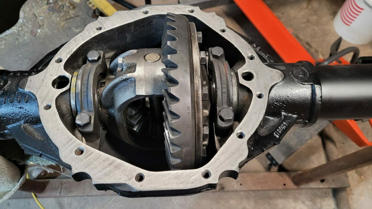
We then installed the differential. Because we are using the same carrier, we tried to use the original shims as a starting point but they were too thick. We removed one of the shims and measured it with our calipers to check its thickness and then got some shims from our shim kit we had purchased to come up with a shim pack just slightly smaller than the original. This seemed to work for a start. We placed the bearing caps on the differential end bearings and torqued the cap bolts to 60 ft lbs.

At this point you should be able to move the ring gear back and forth just a tiny bit either way, without it turning the pinion. You should hear a slight ticking noise as you rock it back and forth making contact with the pinion. This is the backlash. This tiny amount of movement needs to be measured with a dial gauge and magnetic base. The backlash setting we are trying to achieve is .006″ – .010″ of movement. This is where the shim adjustment comes into play. If there is no movement then there is not enough backlash and things are too tight. The differential needs to be shimmed away from the pinion. If there is too much backlash then things are too loose and the differential needs to be shimmed closer to the pinion.
Once the backlash is adjusted properly, then we need to check the contact pattern of the gears and again make adjustments if necessary. To do this you will need some gear marking paste. A little of this seems to go a long way. We spread the paste on about 3 or 4 of the ring gear teeth, not real thick but just enough to coat the gears. We then roll the ring around to where the area with the paste is making contact with the pinion gear. Now holding some pressure on the ring gear, turn the pinion back and forth to make an impression in the paste. When you turn the ring back out so you can view the area with the applied marking paste, you should see something similar to the picture below.

The dark area that is highlighted, is where the ring gear is making contact with the pinion. This photo was taken after making some adjustments to shims. We needed to add .020″ of shims under the inner pinion bearing, to bring the pinion gear up closer to the differential. After doing this we needed to reduce some of the shims we had placed behind the carrier bearings to get our backlash back to .006″. One thing to remember is to be accurate you need to check the contact pattern with everything tightened to specs the way it would be after final assembly. Here is a chart to aid in making adjustments to the contact pattern for the ring and pinion gears.

Once we get the ring gear contact pattern set correctly and the backlash within tolerances then we should be ready for final assembly. You may need to remove the differential one last time to be able to replace the the modified outer pinion bearing with an unmodified one. Before putting the final outer pinion bearing in place, insert the crush sleeve over the pinion shaft, then put the bearing in place. You may need to start pressing the outer pinion bearing onto the pinion shaft a bit before you are able to install the pinion shaft seal. Add thread locker to the threads of the pinion before installing the pinion nut and tightening to final torque specs. We can then place the differential back in the housing and replace the carrier bearing caps. Once again thread locker on the differential bearing cap bolts before final torque.
This is as far as we can go until we get the backing plates and brakes installed on the axle. You can read about that in the next post.